The aircraft is equipped with two identical air condition systems using bleed
air from the pneumatic system to supply pressurized conditioned air to the cabin
and flight deck area.
The systems are designed for independent or parallel operation. Normally the right
system uses bleed air from the right engine and the left system from the left engine.
The air is supplied from the 8th stage and the 13th stage of the engine compressor,
as required by pneumatic power demand.
Each system has an automatic temperature control designed to provide individual
temperature selection for the cabin and flight deck. The cabin air temperature demand
governs the output of the right system, and the flight deck temperature demand
governs the left system. the temperature control systems can also be operated
manually.
Both systems will be automatically shut off in the event of an engine failure provided
the air condition AUTO SHUT OFF SWITCH is in ARM position. This is to obtain
maximum thrust from the remaining engine. When reversing, both systems will be
shut off, to prevent exhaust fumes from entering the aircraft.
On ground with the engines stopped, the air conditioning systems can be operated
by using bleed air from the APU. Outside air can be used to ventilate the aircraft
on ground via the RAM AIR switch.
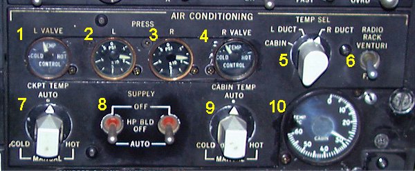
- 1. VALVE POSITION ONDICATOR left system.
- Indicate actual position of the left temperature control valve. Pointer
at COLD indicates valve fully closed and at HOT valve is fully opened.
- 2. SUPPLY AIR PRESSURE INDICATOR left system.
- Indicates the supply air pressure available.
- 3. SUPPLY AIR PRESSURE INDICATOR right system.
- 4. VALVE POSITION ONDICATOR right system.
-
- 5. TEMP LELECTOT SWITCH.
- Permits selection of CABIN, L or R DUCT temperature for display
on adjacent temperature indicator (10).
- 6. RADIO RACK FAN switch.
- - VENTURI. The fan is stopped and the air is discharged through the venturi.
NO heating of the forward cargo compartment.
- FAN. Fan operation is continuous. The air is routed from the ELECTRONIC
COMPARTEMENT into the forward cargo compartment. Thus providing heating of
this compartment (also called ANIMAL COMPARTMENT). -
7. COCKPIT TEMP SELECTOR Left air condition system.
- The AUTO range provides automatic temperature control. Temperature selection
is made by rotating the knob towards HOT or COLD.
In MANUAL range the temperature control valve is manually controlled. -
8. AIR CONDITION SUPPLY switches. Left and Right air condition system.
- - OFF. Closes the pressure regulator and flow control valve. Disarmes
the augmentation valve (13th stage valve).
- HP BLD OFF. Opens the pressure regulator and flow control valve. Maintains the
augmentation valve disarmed. Start the heat exchanger cooling fan on ground.
- AUTO. Same as HP BLD OFF except that the augmentation valve is armed.
- 9. CABIN TEMP SELECTOR Right air condition system.
- 10. TEMPERATURE INDICATOR.
- Shows the temperature at the location selected by the temperature
indicator selector (5).
Normal operation.
Try to obtain an indicated cabin temperature of +24şC. APU air may be used on
ground only. To save fuel the APU AIR switch should, whenever possible, be in
position AIR COND COLDER. This position will give less airflow but colder air
and will require less demand from the APU.
In order to increase airflow and heating capacity, position ON may be used at
low OAT.
To prevent cold drafts in one side of the cabin, do not allow the temperature
control valves to take extreme opposite position. If too large differences
occur, adjust the left system to obtain a duct temperature of +5 - +15°C. The
right system will then automatically adjust to ensure proper cabin temperature.
GROUND VENTILATION (no engine/APU air).
Ground ventilation is the most economical way of air conditioning cabin/flight deck.
The air temperature increases approximately 7şC when passing through right
ground blower.
- APU AIR switch
- AIR CONDITIONING SUPPLY switches
- RAM AIR switch
|
OFF.
LEFT OFF
RIGHT HP BLD OFF.
ON.
|
GROUND VENTILATION (using APU AIR only).
Cabin temperature below 25şC
- APU AIR switch
- PNEU X-FEED VALVE levers L and R
- AIR CONDITION SUPPLY switches
- CABIN/CKPT TEMP selectors
|
AIR COND COLDER.
OPEN.
LEFT OFF.
RIGHT ON.
AUTO.
|
With the APU AIR switch in AIR COND COLDER position, the airflow may be
increased by setting RAM AIR switch in ON. This is advisable at OAT between
0ş and + 20şC.
Cabin temperature above 25şC
- APU AIR switch
- PNEU X-FEED VALVE levers, L and R
- AIR CONDITION SUPPLY switches L and R
- CABIN/CKPT temp selectors
|
AIR COND COLDER.
OPEN.
HP BLD OFF.
AUTO.
|
OPERATION WITH ENGINE BLEED AIR
- APU AIR switch
- PNEU X-FEED VALVE L and R
- AIR CONDITIONING SUPPLY switches L and R
- CABIN AND CKPT TEMP selectors
-AIR COND AUTO SHUTOFF switch
|
OFF
CLOSE
AUTO
AUTO
ARM
|
During climb and cruise before reaching 10 000ft
| - AIR COND AUTO SHUTOFF switch |
OVRD |
SUPPLEMENTAL AIR CONDITIONING
During low thrust engine operation on ground, engine bleed air may be
insufficient to achieve effective air conditioning. The APU may be utilized
as a supplemental air source. The following procedure shall be used.
- Set L PNEU X-FEED VALVE lever to
- Set R PNEU X-FEED VALVE lever to
- APU AIR switch
- CKPT and CABIN TEMP selectors
|
OPEN
CLOSE
ON
AUTO
|
Before takeoff
- APU AIR switch
- APU MASTER switch
- Left PNEU X-FEED VALVE lever
|
OFF.
OFF
CLOSE
|
|