The Auxiliary Power Unit (APU), supplies pneumatic power for engine starting and
for air conditioning on ground as well as electrical power for normal aircraft
system operation on ground. It may also be used as an auxiliary electrical power
source in flight an case of an engine generator malfunction.
Electrical power for starting the APU is taken from the aircraft battery and fuel
is normally supplied from the right main tank.
When starting the APU with battery power only, the
DC START PUMP shall be used. Width external or engine driven generator
power available, one of the right main tank PUMPS
is used for the fuel supply.
The APU is automatically shut down in case of overspeed or fire.
The APU generator gives full output up to 25 000 ft. At 30 000 ft, only 70%
output can be expected.
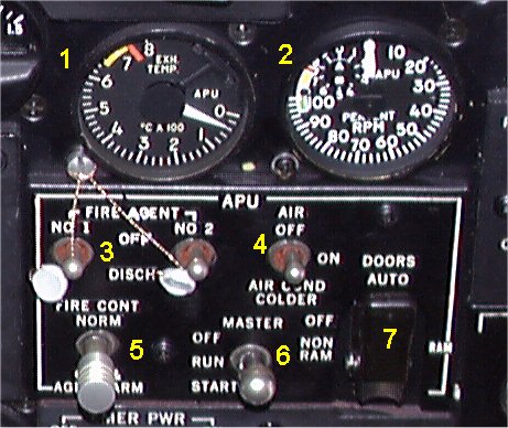
- 1. EGT INDICATOR.
- Indicates exhaust temperature. Max 650şC for continuous load.
- 2. RPM INDICATOR.
- Indicates the rpm as percent of a normal established rpm. Normal load 95%.
- 3. FIRE AGENT switches. FIRE AGENT DISCHARGE switches.
- DISCH position will discharge the selected fire bottle, provided the fire
control switch is in OFF & AGENT ARM position.
- 4. AIR SWITCH.
- In ON position, the load control valve will be energized provided the
APU has reached 95 percent rpm.
In OFF position, the load control valve will be closed.
AIR COND COLDER will give an increased cooling effect on ground.
- 5. FIRE CONT. FIRE CONTROL SWITCH.
- In OFF & AGENT ARM position the following accurs:
- APU is shut off.
- APU generator field will open.
- Fire agent discharge switches in the cockpit are armed.
- External fire agent discharge switches are disarmed.
NORM position provides power for the external fire discharge circuit and disarms
the discharge switches in the cockpit.
- 6. MASTER SWITCH .
- In OFF position, fuel, ignition and starter circuits are de-energized
and inlet doors closing circuits armed.
In START position, starter, door control and oil pressure sequence switch will
be energized.
RUN position retains the inlet doors circuit, fuel (and ignition up to 95% rpm)
and arms the bleed air load control.
A WARMUP and SHUTDOWN DELAY RELAY will provide a 60 seconds warmup period
before bleed air extraction is begun. If bleed air has been used, the relay
automatically provides a 60 seconds cooldown after master switch has been set to OFF.
- 7. DOOR SWITCH.
- In position AUTO (guarded), it selects non-ram and ram door positions
automatically for ground and inflight starting.
Position NO RAM and RAM manually selects the respective inlet door position.
In position OFF, the door control circuits are de-energized.
|