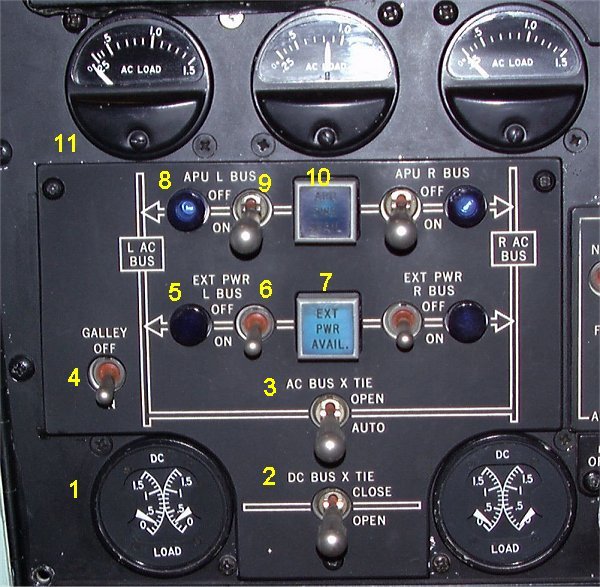
- 1. DC LOAD METER.
- Four Transformer Rectifiers (TR) provide the main source of DC power to the system.
The left and right DC systems operate independently of each other but can be
manually interconnected by the DC crosstie switch, in case of loss of DC power
on either side.
- 2. DC BUS CROSSTIE SWITCH.
- In position CLOSE it connects the L DC bus and R DC bus allowing any combination
of transformer rectifiers to power both DC buses. In position OPEN, the buses
are separated and powered from their respective TR. The switch is normally
placed in OPEN and should only be placed in position CLOSED, when so required
by the EMERGENCY checklist.
- 3. AC BUS CROSSTIE SWITCH.
- In OPEN position, the crosstie relay will always be open. In position
AUTO, the relay will close automatically if one bus system looses its power
supply and the conditions for bus interconnection are satisfied. The switch is
normally placed in AUTO.
- 4. GALLEY POWER SWITCH.
- 5. EXT PWR. POWER IN USE LIGHT.
- Blue light indicates that the external power is connected to the bus.
- 6. EXTERNAL POWER BUS SWITCH.
- Selects external power to the respective bus system.
- 7. EXTERNAL POWER AVAILABLE LIGHT.
- Indicates that external power is available.
In this picture the light is ON but the POWER IN USE light is black, indicating
that EXT PWR is available but the APU is connected to the buses.
- 8. APU PWR. POWER IN USE LIGHT.
- Blue light indicates that the APU power is connected to the bus.
- 9. APU BUS SWITCH.
- In ON position it connects the APU generator to associated bus if this
bus is not already energized by its own generator.
- 10. APU PWR AVAILABLE LIGHT.
- Indicates that APU power is available.
- 11. AC LOAD METER. One for each generator.
- Indicates generator output in terms of generator rating. 1.0 corresponds
to 40 KVA. Max continuous reading - 1.0. Overload for 5 minutes - 1.5.
|