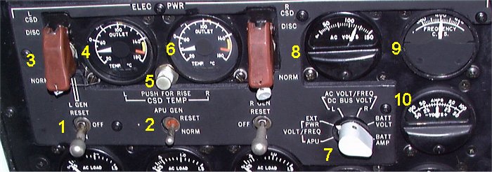
- 1. L GEN and R GEN. Left and right generator switches
- Controls the generator relay (GR). In OFF position, the GR will always
be open. In ON position, the GR will normally be closed, providing no faulty
condition exist. When held in REST position, it rests generator control circuit.
- 2. APU GEN. APU generator switch
- In NORM position, the generator will be connected to desired AC bus if APU
is running and no fault condition exist. When held in RESET, it resets generator
control circuit.
- 3. L CSD DISC and R CSD DISC. Left and right CSD disconnect switches.
- Guarded in NORM position. When switch is placed in DISC position, the CSD
will be mechanically disconnected and cannot be reconnected in flight.
Each engine driven generator is connected to its engine through a hydro-mechanical
constant speed drive (CSD). The CSD system maintains a constant generator speed of
6000 rpm at any engine speed.
- 4. L CSD OIL TEMP INDICATOR.
- Indicates CSD oil outlet temperature on the inner scale. When button (6)
is depressed, displays temperature rise across the CSD on the outer scale.
- 5. PUSH FOR RISE.
- 6. R CSD OIL TEMP INDICATOR.
- Selects external power to the respective bus system.
- 7. METER SELECTOR.
- Selects output to indicator 8, 9 and 10.
- 8. AC VOLTMETER.
- Indicates voltage output of the generators or external power as selected by
the meter selector (7).
- 9. AC FREQUENCY METER.
- Indicates frequency output of the generators or external power as selcted
by the meter selector (7).
- 10. DC VOLT/AMP METER.
- Indicates battery charging or discharging current, battery voltage or
DC bus voltage as selected by the meter selector (7).
|