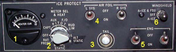
Ice protection panel.
The purpose of the ice and rain protection system is to protect the aircraft from icing in certain critical areas and to improve visibility through the windshields during adverse weather conditions. Hot air from the pneumatic system, as well as electrical power, is used to operate the various subsystems as follows; - Bleed air from the 8th compressor stage, augmented as necessary by air from 13th compressor stage is used to anti-ice the wing leading edge, the stabilizer leading edge and the air condition system ram air intake. - 8th stage bleed air is used for anti-icing of the engine nose bullet and the compressor inlet guide vans. - 13th stage bleed air is used for nose cowl anti-icing. - Electrical power is used to heat the windshields for anti-icing, anti-fogging and added strength. Electrical power also operates the windshield wipers. - Electrical power is used to anti-ice all pitot tubes, static ports, angle-of- attack sensors and the ram air temperature probe. - Electrical power is used to anti-ice the fresh water servicing panel.
General recommendations.- Takeoff is allowed with a layer of frost not exceeding 3 mm on the underside of the wing tank area. Outside this area no frost is permitted.- Turn on the airfoil anti-ice protection before entering conditions which are favourable to icing and when actual icing is experienced. It is recommended that airfoil anti-ice is turned on whenever flying in clouds with RAT between +6ş and -10şC. - During flight in continuous icing conditions, operate the tail de-ice system approximately every 20 minutes and also one minute before final flap setting i.e. in connection with landing gear extension. - On ground, switch on the airfoil anti-ice system, if icing conditions is suspected at or below flap retraction altitude, in connection with engine failure. - Engine anti-ice shall be turned on at any time during ground and flight operations when icing conditions exist or are anticipated. - Engine anti-ice shall be turned on during GROUND OPERATION (use OAT), takeoff and approach (use RAT) whenever the temperature is +6ş or less and dewpoint is at or within 3şC of ambient temperature or moist conditions present (such as rain, sleet, snow, fog or water, ice on the taxiway or runway). - Engine anti-ice shall be turned on before entering clouds when RAT is between +6şC and - 10şC. - During ground operation in high moisture conditions and temperature below +2şC the engine anti-icing system may not be capable of keeping the engines clear of ice during prolonged taxiing/and or long periods of idling. Periodic engine run-up (70% N1 for a minimum of 15 seconds) shall be performed in these conditions. Normally such run-ups need not be made more frequently than at 10 minutes intervals. - Takeoff under these icing conditions shall always be preceded by an engine run-up as above, with observation of EPR and EGT to assure normal engine operation. - In flight, it is recommended to keep EPR at or above 1,2 to achieve sufficient heating of the inlet when the engine anti-ice system is on. - Engine anti-ice switches shall be operated one at a time to prevent surging of both engines simultaneously and also prevent surges in pneumatic system. |