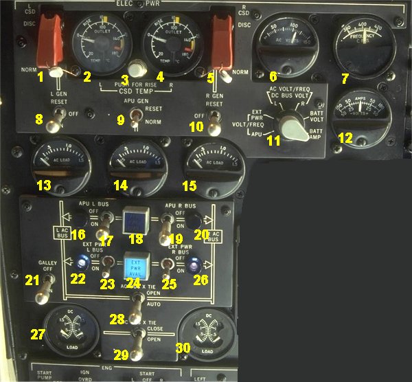
- 1. L CSD DISC. Left CSD disconnect switch.
- Guarded in NORM position. When switch is placed in DISC position, the CSD
will be mechanically disconnected and cannot be reconnected in flight.
Each engine driven generator is connected to its engine through a hydro-mechanical
constant speed drive (CSD). The CSD system maintains a constant generator speed of
6000 rpm at any engine speed.
- 2. L CSD OIL TEMP INDICATOR.
- Indicates CSD oil outlet temperature on the inner scale. When button (3)
is depressed, displays temperature rise across the CSD on the outer scale.
- 3. PUSH FOR RISE.
- 4. R CSD OIL TEMP INDICATOR.
- 5. R CSD DISC. Right CSD disconnect switch.
- 6. AC VOLTMETER.
- Indicates voltage output of the generators or external power as selected by
the meter selector (7).
- 7. AC FREQUENCY METER.
- Indicates frequency output of the generators or external power as selcted
by the meter selector (7).
- 8. L GEN. Left generator switch
- Controls the generator relay (GR). In OFF position, the GR will always
be open. In ON position, the GR will normally be closed, providing no faulty
condition exist. When held in REST position, it rests generator control circuit.
- 9. APU GEN. APU generator switch
- In NORM position, the generator will be connected to desired AC bus if APU
is running and no fault condition exist. When held in RESET, it resets generator
control circuit.
- 10. R GEN. Right generator switch
- 11. METER SELECTOR.
- Selects output to indicator 6, 7 and 12.
- 12. DC VOLT/AMP METER.
- Indicates battery charging or discharging current, battery voltage or
DC bus voltage as selected by the meter selector (11).
- 13. AC LOAD METER. Left generator.
- Indicates generator output in terms of generator rating. 1.0 corresponds
to 40 KVA. Max continuous reading - 1.0. Overload for 5 minutes - 1.5.
- 14. AC LOAD METER. APU generator.
- 15. AC LOAD METER. Right generator.
- 16. APU PWR. POWER IN USE LIGHT left bus.
- Blue light indicates that the APU power is connected to the left bus.
- 17. APU BUS SWITCH left bus.
- In ON position it connects the APU generator to associated bus if this
bus is not already energized by its own generator.
- 18. APU PWR AVAILABLE LIGHT.
- Indicates that APU power is available.
- 19. APU BUS SWITCH right bus.
- 20. APU PWR. POWER IN USE LIGHT right bus.
- 21. GALLEY POWER SWITCH.
- 22. EXT PWR. POWER IN USE LIGHT left bus.
- Blue light indicates that the EXTERNAL power is connected to the left bus.
- 23. EXT BUS SWITCH left bus.
- In ON position it connects the EXT power to associated bus if this
bus is not already energized by its own generator.
- 24. EXT PWR AVAILABLE LIGHT.
- Indicates that EXT power is available.
- 25. EXT BUS SWITCH right bus.
- 26. EXT PWR. POWER IN USE LIGHT right bus.
- 27. DC LOAD METER TR 1 and 2.
- Four Transformer Rectifiers (TR) provide the main source of DC power to the system.
The left and right DC systems operate independently of each other but can be
manually interconnected by the DC crosstie switch, in case of loss of DC power
on either side.
- 28. AC BUS CROSSTIE SWITCH.
- In OPEN position, the crosstie relay will always be open. In position
AUTO, the relay will close automatically if one bus system looses its power
supply and the conditions for bus interconnection are satisfied. The switch is
normally placed in AUTO.
- 29. DC BUS CROSSTIE SWITCH.
- In position CLOSE it connects the L DC bus and R DC bus allowing any combination
of transformer rectifiers to power both DC buses. In position OPEN, the buses
are separated and powered from their respective TR. The switch is normally
placed in OPEN and should only be placed in position CLOSED, when so required
by the EMERGENCY checklist.
- 30. DC LOAD METER TR 3 and 4.
|